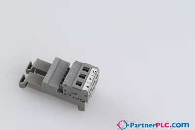
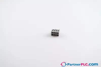
Stackable PCB terminal block; 2.5 mm²; Pin spacing 10/10.16 mm; 1-pole; PUSH WIRE®; gray
Poproś o wycenę



Najważniejsze informacje
| Dostępność | Potwierdzenie na zapytanie |
| Kategoria | PCB Terminal Blocks and Pluggable Connectors |
| Cykl życia | active |
| Gwarancja | 12 miesięcy (nowe) · 3 miesiące (używane/odnowione) |
Wysyłka i dostępność
Kiedy 254-651 może zostać wysłany?
254-651 jest sprowadzany na zamówienie — poproś o wycenę, a potwierdzimy dokładną dostępność i czas realizacji dla tej konkretnej sztuki.
Czy mogę odebrać 254-651 osobiście?
Odbiór osobisty w naszym magazynie w Groningen w Holandii może być możliwy — skontaktuj się z nami przed złożeniem zamówienia, aby potwierdzić dostępność i ustalić termin odbioru.
Czy dostępna jest dostawa ekspresowa?
Tak — wspomnij o tym w zapytaniu ofertowym dotyczącym 254-651, a w odpowiedzi podamy opcje dostawy ekspresowej.
Nasz zakład stoi i pilnie tego potrzebujemy — czy możecie pomóc?
W przypadku krytycznej awarii skontaktuj się z nami bezpośrednio pod numerem +31 (0)50-7110348 lub e-mailem sales@partnerplc.com — sprawdzimy możliwość kuriera tego samego dnia lub dedykowanego transportu dla 254-651, w zależności od dostępności i miejsca docelowego.
<h2>PCB terminal block, 254 Series, with 10 mm pin spacing</h2><br/><br/>This PCB terminal block (item number 254-651) is designed for easy and secure connections. You can count on proven safety with these PCB terminal blocks, perfect for a wide variety of applications when designing your devices. Conductors should only be connected to this PCB terminal block if their strip length is between 10 and 12 mm . This product features one conductor terminal and utilizes PUSH WIRE®. Our PUSH WIRE® connection is the quick and easy method for connecting solid conductors. The dimensions are (11.7 x 19.7 x 13.5) mm (width x height x depth). Depending on the conductor type, this PCB terminal block is ideal for conductor cross sections ranging from 0.5 mm² to 2.5 mm².<br/><br/><h3></h3><br/><br/>Tin is used for coating the contact surfaces. An operating tool is used to operate this PCB terminal block. THT is used to assemble the PCB terminal block. The conductor is designed to be inserted at an angle of 45°..<br/>
Specyfikacja
Notes
| Variants: | Other colors, Versions for Ex i, Other versions (or variants) can be requested from WAGO Sales or configured at https://configurator.wago.com/. |
Electrical data - Ratings per IEC/EN
| Ratings per | IEC/EN 60664-1 |
| Nominal voltage (III/3) | 630 V |
| Rated impulse withstand voltage (III / 3) | 8 kV |
| Rated voltage (III/2) | 1000 V |
| Rated impulse withstand voltage (III/2) | 8 kV |
| Nominal voltage (II/2) | 1000 V |
| Rated impulse withstand voltage (II/2) | 8 kV |
| Rated current | 24 A |
| Legend (ratings) | (III / 2) ≙ Overvoltage category III / Pollution degree 2 |
| Ratings per | IEC/EN 60664-1 / IEC/EN 60664-1 / IEC/EN 60664-1 |
| Overvoltage category | III / III / II |
| Pollution degree | 3 / 2 / 2 |
| Nominal voltage | 630 V / 1000 V / 1000 V |
| Rated impulse withstand voltage | 8 kV / 8 kV / 8 kV |
| Rated current | 24 A / 24 A / 24 A |
Electrical data - Ratings per UL
| Approvals per | UL 1059 |
| Rated voltage UL (Use Group B) | 300 V |
| Rated current UL (Use Group B) | 10 A |
| Rated voltage UL (Use Group D) | 300 V |
| Rated current UL (Use Group D) | 10 A |
| Approvals per | UL 1059 / UL 1059 / UL 1059 |
| Use group | B / C / D |
| Rated voltage | 300 V / 300 V |
| Rated current | 10 A / 10 A |
Electrical data - Ratings per CSA
| Approvals per | CSA |
| Rated voltage CSA (Use Group B) | 300 V |
| Rated current CSA (Use Group B) | 10 A |
| Rated voltage CSA (Use Group D) | 300 V |
| Rated current CSA (Use Group D) | 10 A |
| Approvals per | CSA / CSA / CSA |
| Use group | B / C / D |
| Rated voltage | 300 V / 300 V |
| Rated current | 10 A / 10 A |
Connection data
| Clamping units | 1 |
| Total number of potentials | 1 |
| Number of connection types | 1 |
| Number of levels | 1 |
Connection data - Connection 1
| Connection technology | PUSH WIRE® |
| Actuation type | Operating tool |
| Solid conductor | 0.5 … 2.5 mm² / 20 … 12 AWG |
| Fine-stranded conductor; with insulated ferrule | 0.5 … 1.5 mm² |
| Fine-stranded conductor; with uninsulated ferrule | 0.5 … 1.5 mm² |
| Note (conductor cross-section) | 12 AWG: THHN, THWN |
| Strip length | 10 … 12 mm / 0.39 … 0.47 inches |
| Conductor connection direction to PCB | 45 ° |
| Pole number | 1 |
Physical data
| Pin spacing | 10/10.16 mm / 0.394/0.4 inches |
| Width | 11.7 mm / 0.461 inches |
| Height | 19.7 mm / 0.776 inches |
| Height from the surface | 15.7 mm / 0.618 inches |
| Depth | 13.5 mm / 0.531 inches |
| Solder pin length | 4 mm |
| Solder pin dimensions | 0.5 x 0.75 mm |
| Drilled hole diameter with tolerance | 1.1 (+0.1) mm |
PCB contact
| PCB contact | THT |
| Solder pin arrangement | within the terminal block (in-line) |
| Number of solder pins per potential | 2 |
Material data
| Note (material data) | Information on material specifications can be found here |
| Color | gray |
| Material group | I |
| Insulation material (main housing) | Polyamide (PA66) |
| Flammability class per UL94 | V0 |
| Clamping spring material | Chrome-nickel spring steel (CrNi) |
| Contact material | Electrolytic copper (ECu) |
| Contact plating | Tin |
| Fire load | 0.031 MJ |
| Weight | 1.5 g |
Environmental requirements
| Limit temperature range | -60 … +105 °C |
Commercial data
| Product Group | 4 (Printed Circuit Connectors) |
| PU (SPU) | 300 (100) pcs |
| Packaging type | box |
| Country of origin | PL |
| GTIN | 4044918941013 |
| Customs tariff number | 85369010000 |
Product Classification
| UNSPSC | 39121409 |
| eCl@ss 10.0 | 27-44-04-01 |
| eCl@ss 9.0 | 27-44-04-01 |
| ETIM 9.0 | EC002643 |
| ETIM 10.0 | EC002643 |
| ECCN | NO US CLASSIFICATION |
Environmental Product Compliance
| RoHS Compliance Status | Compliant,No Exemption |