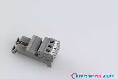
Control Signal Terminal Strip; Enercity Netz Version; according to § 9 EEG
Richiedi un preventivo



In breve
| Disponibilità | Conferma su richiesta |
| Categoria | Rail-Mount Terminal Blocks |
| Ciclo di vita | active |
| Garanzia | 12 mesi (nuovo) · 3 mesi (usato/rigenerato) |
Spedizione e disponibilità
Quando può essere spedito 821-501?
821-501 viene reperito su richiesta — richiedi un preventivo e ti confermeremo disponibilità e tempi di consegna esatti per questa unità specifica.
Posso ritirare 821-501 di persona?
Il ritiro presso il nostro magazzino di Groningen, Paesi Bassi, potrebbe essere possibile — contattaci prima dell'ordine per verificare disponibilità e concordare un orario di ritiro.
È disponibile la consegna espressa?
Sì — menzionalo nella richiesta di preventivo per 821-501 e includeremo le opzioni di spedizione espressa nella nostra risposta.
Il nostro impianto è fermo e ci serve con urgenza: potete aiutarci?
In caso di guasto critico, contattaci direttamente al +31 (0)50-7110348 o a sales@partnerplc.com — valuteremo un corriere in giornata o una consegna dedicata per 821-501, in base a disponibilità e destinazione.
<p><b>Control Signal Terminal Strips per § 9 EEG</b></p><p> </p><p>Due to the requirements of § 9 of the Renewable Energy Act (EEG), operators of, e.g., PV systems or CHPs are obligated to make their feed-in systems remotely controllable for the energy operator or direct marketer. Grid fluctuations or failures caused by feed-in power levels that are too high are to be avoided in order to protect the electrical grid. In consultation and cooperation with various grid operators, these Control Signal Terminal Strips were developed in order to create a uniform standard according to the valid TCRs, which is quick and easy for the system installer to install. These sets are essential for standard-compliant system design as a central connection point between the control unit and the supply system.</p><p>These sets are delivered ready for installation and without a DIN-rail for the end user. They are developed for the German energy market.</p>
Specifiche
Notes
| Note | Set will be delivered without DIN-rail. |
Electrical data - Ratings per IEC/EN
| Ratings per | IEC/EN 60947-7-1 |
| Nominal voltage (III/3) | 800 V |
| Rated impulse withstand voltage (III / 3) | 8 kV |
| Rated current | 24 A |
| Legend (ratings) | (III / 3) ≙ Overvoltage category III / Pollution degree 3 |
Electrical data - Ratings per UL
| Approvals per | UL 1059 |
| Rated voltage UL (Use Group B) | 600 V |
| Rated current UL (Use Group B) | 20 A |
| Rated voltage UL (Use Group C) | 600 V |
| Rated current UL (Use Group C) | 20 A |
Electrical data - Ratings per CSA
| Approvals per | CSA 22.2 No 158 |
| Rated voltage CSA (Use Group B) | 600 V |
| Rated current CSA (Use Group B) | 20 A |
| Rated voltage CSA (Use Group C) | 600 V |
| Rated current CSA (Use Group C) | 20 A |
Electrical data - Ex information
| Reference to hazardous areas | See “Downloads – Documentation – Additional Information: Technical Section; Technical Explications” |
| Ratings per | ATEX: PTB 18 ATEX 1005 U / IECEx: PTB 18.0012U (Ex eb IIC Gb) |
| Rated voltage EN (Ex e II) | 550 V |
| Rated current (Ex e II) | 22 A |
| Rated current (Ex e II) with jumper | 20 A |
Electrical data - Power Loss
| Power loss, per pole (potential) | 0.766 W |
| Rated current I<sub>N</sub> for power loss specification | 24 A |
| Resistance value for specified, current-dependent power loss | 0.001 Ω |
Electrical data - General information
| Wiring direction | Front-entry wiring |
Connection data
| Clamping units | 26 |
| Total number of potentials | 13 |
| Number of levels | 1 |
| Number of jumper slots | 26 |
Connection data - Connection 1
| Connection technology | Push-in CAGE CLAMP® |
| Actuation type | Push-button |
| Connectable conductor materials | Copper |
| Nominal cross-section | 2.5 mm² |
| Solid conductor | 0.25 … 4 mm² / 18 … 12 AWG |
| Solid conductor; push-in termination | 0.75 … 4 mm² / 18 … 12 AWG |
| Fine-stranded conductor | 0.25 … 4 mm² / 22 … 12 AWG |
| Fine-stranded conductor; with insulated ferrule | 0.25 … 2.5 mm² / 22 … 14 AWG |
| Fine-stranded conductor; with ferrule; push-in termination | 1 … 2.5 mm² / 18 … 14 AWG |
| Note (conductor cross-section) | Depending on the conductor characteristic, a conductor with a smaller cross-section can also be inserted via push-in termination. |
| Strip length | 10 … 12 mm / 0.39 … 0.47 inches |
| Wiring direction | Front-entry wiring |
Physical data
| Width | 80.4 mm / 3.165 inches |
| Height | 48.5 mm / 1.909 inches |
| Depth from upper-edge of DIN-rail | 32.9 mm / 1.295 inches |
| Depth | 39.5 mm / 1.555 inches |
Mechanical data
| Mounting type | DIN-35 rail |
Material data
| Note (material data) | Information on material specifications can be found here |
| Material group | I |
| Insulation material (main housing) | Polyamide (PA66) |
| Flammability class per UL94 | V0 |
| Fire load | 1.888 MJ |
| Weight | 79.8 g |
Environmental requirements
| Processing temperature | -35 … +85 °C |
| Continuous operating temperature | -60 … +105 °C |
Commercial data
| PU (SPU) | 1 pcs |
| Packaging type | Box |
| Country of origin | DE |
| GTIN | 4066966654059 |
| Customs tariff number | 85369010000 |
Product Classification
| ETIM 9.0 | EC000897 |
| ETIM 10.0 | EC000897 |
| ECCN | NO US CLASSIFICATION |
Environmental Product Compliance
| RoHS Compliance Status | Compliant,No Exemption |