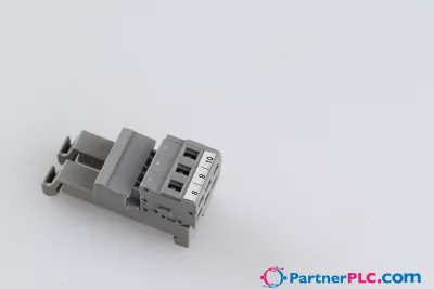
Bus Extension Coupler Module
Richiedi un preventivo



In breve
| Disponibilità | Conferma su richiesta |
| Categoria | I/O Systems |
| Ciclo di vita | active |
| Garanzia | 12 mesi (nuovo) · 3 mesi (usato/rigenerato) |
Spedizione e disponibilità
Quando può essere spedito 750-628?
750-628 viene reperito su richiesta — richiedi un preventivo e ti confermeremo disponibilità e tempi di consegna esatti per questa unità specifica.
Posso ritirare 750-628 di persona?
Il ritiro presso il nostro magazzino di Groningen, Paesi Bassi, potrebbe essere possibile — contattaci prima dell'ordine per verificare disponibilità e concordare un orario di ritiro.
È disponibile la consegna espressa?
Sì — menzionalo nella richiesta di preventivo per 750-628 e includeremo le opzioni di spedizione espressa nella nostra risposta.
Il nostro impianto è fermo e ci serve con urgenza: potete aiutarci?
In caso di guasto critico, contattaci direttamente al +31 (0)50-7110348 o a sales@partnerplc.com — valuteremo un corriere in giornata o una consegna dedicata per 750-628, in base a disponibilità e destinazione.
<p>The 750-628 Coupler Module for Internal Data Bus Extension replaces the fieldbus coupler/controller on a module assembly. It is also the mating piece for the 750-627 End Module. Plug the connection cable into the top RJ-45 socket to establish the logical link to the fieldbus coupler/controller via the 750-627 End Module. <br/>The extension is completely transparent for the fieldbus coupler/controller. All of the functions of the I/O module system are retained without any changes. <br/>A further extension to the system is provided by the bottom RJ-45 socket. This enables the entire system to be extended by 10 stages.</p><p>The supply voltage for the field side and the internal electronics can be input separately. Both levels are electrically isolated from each other. Two diagnostic LEDs give information about the supply voltage for both the internal and field side. Two LEDs in the input socket indicate fault-free communication with the bus coupler. The module can be used as the last coupler module in the system (switch on matching resistor) or as a bridge between two I/O module assemblies.</p><b>Installation note (NOTICE):</b><p>In order to guarantee safe operating conditions when using the 750-627/-628 Coupler Modules for Internal Data Bus Extension, these must be registered prior to startup with the couplers or PLCs (refer to manual for supported couplers/PLCs). You must use the <br/>WAGO Extension Setting Software for this (Download: www.wago.com).</p><p>Please note that only one terminating resistor may be activated in the whole system.</p><p>Please complete the manufacturing number matrix on the right-hand side of the couplers when updating the firmware and internal operating parameters.</p>
Specifiche
Technical data
| Number of modules per node (max.) | 64 |
| Device-specific | Distance (max.): 5 m (10 m see manual); (end/coupler modules or coupler/coupler modules) |
| Transmission medium | Shielded copper cable (ETHERNET patch cable); 4 x 2 x 0.25 mm², twisted pair, double shielding, STP (Shielded Twisted-Pair) |
| Supply voltage (system) | 24 VDC (-15 … +20 %); via pluggable connector (CAGE CLAMP® connection) |
| Input current (typ.) at nominal load (24 V) | 200 mA |
| Power supply efficiency (typ.) at nominal load (24 V) | 76 % |
| Supply voltage (field) | 24 VDC (-15 … +20 %); via power jumper contacts (power supply via CAGE CLAMP® connection; transmission (field-side supply voltage only) via spring contact |
| Current consumption (5 V system supply) | 150 mA |
| Total current (system supply) | 400 mA |
| Current carrying capacity (power jumper contacts) | 10 A |
| Number of outgoing power jumper contacts | 3 |
| Isolation | 500 V system/field |
| Indicators | LED (A, B) green: operating voltage status: system, power jumper contacts |
Connection data
| Connection technology: communication/fieldbus | Local bus: 2 x RJ-45 |
| Connectable conductor materials | Copper |
| Connection type | System/field supply |
| Solid conductor | 0.08 … 2.5 mm² / 28 … 14 AWG |
| Fine-stranded conductor | 0.08 … 2.5 mm² / 28 … 14 AWG |
| Strip length | 8 … 9 mm / 0.31 … 0.35 inches |
| Connection technology: field supply | 6 x CAGE CLAMP® |
| Connection technology: system supply | 2 x CAGE CLAMP® |
Physical data
| Width | 24 mm / 0.945 inches |
| Height | 100 mm / 3.937 inches |
| Depth | 69.8 mm / 2.748 inches |
| Depth from upper-edge of DIN-rail | 62.6 mm / 2.465 inches |
Mechanical data
| Mounting type | DIN-35 rail |
Material data
| Color | light gray |
| Housing material | Polycarbonate; polyamide 6.6 |
| Fire load | 0.016 MJ |
| Weight | 74.8 g |
| Conformity marking | CE |
Environmental requirements
| Ambient temperature (operation) | 0 … +55 °C |
| Ambient temperature (storage) | -40 … +85 °C |
| Protection type | IP20 |
| Pollution degree | 2 per IEC 61131-2 |
| Operating altitude | 0 … 2000 m / 0 … 6562 ft |
| Mounting position | Horizontal left, horizontal right, horizontal top, horizontal bottom, vertical top and vertical bottom |
| Relative humidity (without condensation) | 95 % |
| Vibration resistance | 4g per IEC 60068-2-6 |
| Shock resistance | 15g per IEC 60068-2-27 |
| EMC immunity to interference | per EN 61000-6-2, marine applications |
| EMC emission of interference | per EN 61000-6-4, marine applications |
| Exposure to pollutants | per IEC 60068-2-42 and IEC 60068-2-43 |
| Permissible H<sub>2</sub>S contaminant concentration at a relative humidity <lt/> 75 % | 10 ppm |
| Permissible SO<sub>2</sub> contaminant concentration at a relative humidity <lt/> 75 % | 25 ppm |
Commercial data
| Product Group | 15 (I/O System) |
| PU (SPU) | 1 pcs |
| Packaging type | Box |
| Country of origin | DE |
| GTIN | 4045454830991 |
| Customs tariff number | 85389091890 |
Product Classification
| UNSPSC | 32151705 |
| eCl@ss 10.0 | 27-24-26-10 |
| eCl@ss 9.0 | 27-24-26-10 |
| ETIM 9.0 | EC001600 |
| ETIM 10.0 | EC001600 |
| ECCN | NO US CLASSIFICATION |
Environmental Product Compliance
| RoHS Compliance Status | Compliant,No Exemption |