3-Phase Power Measurement; 690 VAC, 1 A
Richiedi un preventivo



In breve
| Disponibilità | Conferma su richiesta |
| Categoria | I/O Systems |
| Ciclo di vita | active |
| Garanzia | 12 mesi (nuovo) · 3 mesi (usato/rigenerato) |
Spedizione e disponibilità
Quando può essere spedito 750-495?
750-495 viene reperito su richiesta — richiedi un preventivo e ti confermeremo disponibilità e tempi di consegna esatti per questa unità specifica.
Posso ritirare 750-495 di persona?
Il ritiro presso il nostro magazzino di Groningen, Paesi Bassi, potrebbe essere possibile — contattaci prima dell'ordine per verificare disponibilità e concordare un orario di ritiro.
È disponibile la consegna espressa?
Sì — menzionalo nella richiesta di preventivo per 750-495 e includeremo le opzioni di spedizione espressa nella nostra risposta.
Il nostro impianto è fermo e ci serve con urgenza: potete aiutarci?
In caso di guasto critico, contattaci direttamente al +31 (0)50-7110348 o a sales@partnerplc.com — valuteremo un corriere in giornata o una consegna dedicata per 750-495, in base a disponibilità e destinazione.
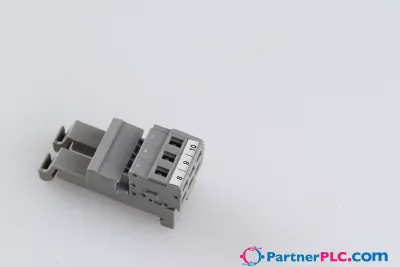
<p>The 750-495 3-Phase Power Measurement Module allows measurement of electrical data in a three-phase supply network.</p><p>The voltage is measured via network connection to L1, L2, L3 and N.</p><p>The current of the three phases is fed to I1, I2, I3 and IN (two clamping points each +,-) via current transformers or via Rogowski coils for the 750-495/000-002 Module.</p><p>The 3-phase power measurement module transmits all metrics (e.g., reactive/apparent/effective power, energy consumption, power factor, phase angle, frequency, over-/undervoltage) directly to the process image, without requiring high computing power from the controller. Both comprehensive metrics and harmonic analysis up to the 41st harmonic permit extensive network analysis via the fieldbus. These metrics enable the operator to optimize supply to a drive or machine, protecting the system from damage and failure. Insulation failures can be detected and prevented via current measurement performed in the neutral conductor. The four-quadrant display indicates the load type (inductive, capacitive) and whether it is an energy consumer or producer.</p>
Specifiche
Technical data
| Number of measurement inputs | 7 (3 voltage measurement inputs, 4 differential current measurement inputs) |
| Signal type | Power measurement |
| Signal form | Sinusoidal signals (taking the cutoff frequency into account) |
| Resolution [bit] | 24 Bit |
| Data width | 2 x 128-bit data; 2 x 64-bit control/status |
| Voltage path input resistance (typ.) | 1429 kΩ |
| Current path input resistance (typ.) | 22 mΩ |
| Reference for measurement error | AC current/voltage |
| Measurement error (reference temperature) | 23 °C |
| Measurement error, deviation (max.) from the upper-range value | 0.5 % |
| Measurement current (max.) | 1 A |
| Measurement cycle time | Adjustable for arithmetic mean value, Min_Max_Values |
| Frequency range (mains frequency) | 50/60 Hz |
| Frequency range (harmonics analysis) | 0 … 3300 Hz |
| Limit frequency | 15.9 kHz |
| Permissible common mains supply systems | Three-phase, four-wire system: max. 277/480 VAC; Three-phase, three-wire system: max. 600 VAC (UL) |
| Note on common mains supply systems | ULL up to 690°V is possible under special conditions (see manual). |
| Upper-range value for the measurement accuracy | 400/690 V |
| Calculated values | Line-to-line voltage, power output, energy, power factors, mains frequency, harmonic analysis (up to the 41st harmonic), THD |
| Measurement method | True RMS measurement |
| Supply voltage (system) | 5 VDC; via data contacts |
| Current consumption (5 V system supply) | 100 mA |
| Indicators | LED (A) green: Communication; LED (B-G) red: Error L1, Override in Current Measurement Path (display), Undervoltage in Voltage Measurement Path (display), Error L2, Error L3, Override in Voltage Measurement Path (display); LED (H) yellow: Interchange in Phase Sequence L1-L2-L3 |
Safety and protection
| Measurement category per EN/UL 61010-2-030 | CAT III |
Safety and protection - Test voltage
| Test voltage | 3.51 kVAC, 50/60 Hz, 1 min. |
| Rated impulse withstand voltage | System/field side: 5.0 kV (EN 60870-2-1 / Class VW3) 6.4 kV (EN/UL 61010-1) |
Safety and protection - Insulation coordination per EN/UL 61010-2-201 with N connection
| System voltage | ≤ 300 V |
| Note on system voltage | The system voltage corresponds to the line-to-neutral voltage derived from conventional mains power supply systems. |
| Overvoltage category | III |
| Insulation type | Reinforced insulation |
Safety and protection - Insulation coordination per EN/UL 61010-2-201 without N connection
| System voltage | ≤ 600 V |
| Note on system voltage | To ensure safe insulation, the module's N connector must not be connected. The system voltage corresponds to the line conductor/neutral conductor voltage, which was derived from standard power supply systems |
| Overvoltage category | III |
| Insulation type | Double isolation (basic isolation and supplementary isolation by impedance/current measurement transformer) Safe isolation from the adjacent SELV/PELV modules must be ensured. The product manual contains the types of isolation to adjacent modules in section “Isolation to Adjacent I/O Modules per EN/UL 61010 2-201.” Without double or reinforced isolation, the 750-495/000-00x Power Measurement Module must not be placed directly next to SELV/PELV modules. Under such conditions, the 750-616 Distance Module must be used. |
Connection data
| Connection technology: I/O | 12 x CAGE CLAMP® |
| Connectable conductor materials | Copper |
| Connection type | Inputs/outputs |
| Solid conductor | 0.08 … 2.5 mm² / 28 … 14 AWG |
| Fine-stranded conductor | 0.08 … 2.5 mm² / 28 … 14 AWG |
| Strip length | 8 … 9 mm / 0.31 … 0.35 inches |
| Note (conductor cross-section) | Solid conductor: 20 … 14 AWG (UL); Fine-stranded conductor: 20 … 16 AWG (UL) These values refer exclusively to the mechanical connection capacity of the clamping points. When the applications/devices are operated in locations covered by UL, only solid conductor with 20 … 14 AWG and fine-stranded conductor with 20 … 16 AWG are permitted. |
Physical data
| Width | 24 mm / 0.945 inches |
| Height | 100 mm / 3.937 inches |
| Depth | 67.8 mm / 2.669 inches |
| Depth from upper-edge of DIN-rail | 60.6 mm / 2.386 inches |
Mechanical data
| Mounting type | DIN-35 rail |
Material data
| Color | light gray |
| Housing material | Polycarbonate; polyamide 6.6 |
| Fire load | 1.445 MJ |
| Weight | 90.7 g |
| Conformity marking | CE |
Environmental requirements
| Ambient temperature (operation) | 0 … +55 °C |
| Ambient temperature (storage) | -40 … +85 °C |
| Protection type | IP20 |
| Pollution degree | 2 per EN 60664-1 |
| Operating altitude | 0 … 2000 m / 0 … 6562 ft |
| Mounting position | Horizontal left, horizontal up, vertical top and vertical bottom |
| Relative humidity (without condensation) | 95 % |
| Vibration resistance | 4g per IEC 60068-2-6 |
| Shock resistance | 15g per IEC 60068-2-27 |
| EMC immunity to interference | per EN 61000-6-2 |
| EMC emission of interference | per EN 61000-6-3 |
| Exposure to pollutants | per IEC 60068-2-42 and IEC 60068-2-43 |
| Permissible H<sub>2</sub>S contaminant concentration at a relative humidity <lt/> 75 % | 10 ppm |
| Permissible SO<sub>2</sub> contaminant concentration at a relative humidity <lt/> 75 % | 25 ppm |
Commercial data
| Product Group | 15 (I/O System) |
| PU (SPU) | 1 pcs |
| Packaging type | Box |
| Country of origin | DE |
| GTIN | 4050821548256 |
| Customs tariff number | 85389099990 |
Product Classification
| UNSPSC | 41113630 |
| eCl@ss 10.0 | 27-24-26-05 |
| eCl@ss 9.0 | 27-24-26-05 |
| ETIM 9.0 | EC001596 |
| ETIM 10.0 | EC001596 |
| ECCN | NO US CLASSIFICATION |
Environmental Product Compliance
| CAS-No. | 1303-86-2, 1317-36-8, 7439-92-1 |
| REACH Candidate List Substance | Diboron trioxide, Lead, Lead monoxide |
| RoHS Compliance Status | Compliant,With Exemption |
| RoHS Exemption | 6(c), 7(a), 7(c)-I, 7(c)-II |
| SCIP notification number (Austria) | 73347190-1d14-4d53-b893-45987f131be2 |
| SCIP notification number (Belgium) | b2a5d208-0d6f-4bdc-a394-413f407d46e2 |
| SCIP notification number (Bulgaria) | 8f76372e-a361-4332-b84a-e0cb7d64c765 |
| SCIP notification number (Czech Republic) | 83fe7f37-f240-420d-a287-d608a03f74cc |
| SCIP notification number (Denmark) | 25a0dad3-1933-4610-be29-18db7583c1f6 |
| SCIP notification number (Finland) | ef73bb0b-867e-497d-9f03-e7004dddab68 |
| SCIP notification number (France) | f0f0014b-ab50-4ff8-b1d5-1b59224e58de |
| SCIP notification number (Germany) | 19c14cd4-2f50-40a7-abc7-fc5d6360de54 |
| SCIP notification number (Hungary) | ce6f7e91-8dc5-454c-85ba-1bba4895e8dd |
| SCIP notification number (Italy) | 44eaf31b-582a-4fca-a5da-e77f4dfb7ef8 |
| SCIP notification number (Netherlands) | 9b65d4eb-385b-4784-8729-f96a0e24ffd8 |
| SCIP notification number (Poland) | bcf60c77-e84b-4feb-aef4-71b0d184405f |
| SCIP notification number (Romania) | a3ff47f5-eb1b-4722-bec7-b95d0c19a5fb |
| SCIP notification number (Sweden) | a70ee5c9-ffb6-4f35-a7e2-17d5cf4a0240 |