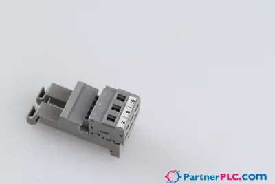
3-conductor ground terminal block; with push-button; 16 mm²; with test port; side and center marking; for DIN-rail 35 x 15 and 35 x 7.5; Push-in CAGE CLAMP®; 16,00 mm²; green-yellow
Richiedi un preventivo



In breve
| Disponibilità | Conferma su richiesta |
| Categoria | Rail-Mount Terminal Blocks |
| Ciclo di vita | active |
| Garanzia | 12 mesi (nuovo) · 3 mesi (usato/rigenerato) |
Spedizione e disponibilità
Quando può essere spedito 2216-1307?
2216-1307 viene reperito su richiesta — richiedi un preventivo e ti confermeremo disponibilità e tempi di consegna esatti per questa unità specifica.
Posso ritirare 2216-1307 di persona?
Il ritiro presso il nostro magazzino di Groningen, Paesi Bassi, potrebbe essere possibile — contattaci prima dell'ordine per verificare disponibilità e concordare un orario di ritiro.
È disponibile la consegna espressa?
Sì — menzionalo nella richiesta di preventivo per 2216-1307 e includeremo le opzioni di spedizione espressa nella nostra risposta.
Il nostro impianto è fermo e ci serve con urgenza: potete aiutarci?
In caso di guasto critico, contattaci direttamente al +31 (0)50-7110348 o a sales@partnerplc.com — valuteremo un corriere in giornata o una consegna dedicata per 2216-1307, in base a disponibilità e destinazione.
<h2>Ground terminal block, 2216 Series, green-yellow</h2><br/><br/>This ground terminal block (item number 2216-1307) is designed for quick and easy connections. Ensure that the strip lengths are between 18 and 20 mm when connecting conductors to this ground terminal block. Our ground terminal blocks allow you to connect electrical conductors directly to the mounting rail thanks to an integrated contact foot. This connection ensures both electrical and mechanical stability between the conductors and the mounting adapter. This product incorporates conductor terminals and utilizes Push-in CAGE CLAMP®. Push-in CAGE CLAMP® technology provides a universal connection solution for any type of conductor. It allows both solid and fine-stranded conductors with ferrules to be inserted directly into the clamping point without the need for tools. This ground terminal block is suitable for conductor cross sections ranging from 0.5 mm² to 16 mm².<br/><br/><h3></h3><br/><br/>A push-button is used to operate this through rail-mount terminal block. Our TOPJOB® S rail-mount terminal blocks guarantee secure electrical connections in different industrial applications and modern building installations. They make wiring work easier as you can quickly plug in solid, stranded, and fine-stranded conductors with ferrules. This product is designed for specific Ex applications (please refer to the product datasheet).<br/>
Specifiche
Electrical data - Ratings per IEC/EN
| Ratings per | IEC/EN 60947-7-2 |
| Ratings per | IEC/EN 60947-7-2 / IEC/EN 60947-7-2 / IEC/EN 60947-7-2 |
| Overvoltage category | III / III / II |
| Pollution degree | 3 / 2 / 2 |
Electrical data - Ratings per IEC/EN – Notes
| Rated current (note) | 15 mm high DIN-35 rails shall be used for a current load higher than 76 A! |
Electrical data - Ex information
| Reference to hazardous areas | See “Downloads – Documentation – Additional Information: Technical Section; Technical Explications” |
Electrical data - General information
| Wiring direction | Front-entry wiring |
Connection data
| Clamping units | 3 |
| Total number of potentials | 1 |
| Number of levels | 1 |
| Number of jumper slots | 2 |
Connection data - Connection 1
| Connection technology | Push-in CAGE CLAMP® |
| Actuation type | Push-button |
| Connectable conductor materials | Copper |
| Nominal cross-section | 16 mm² |
| Solid conductor | 0.5 … 16 mm² / 20 … 6 AWG |
| Solid conductor; push-in termination | 2.5 … 16 mm² / 14 … 6 AWG |
| Fine-stranded conductor | 0.5 … 25 mm² / 20 … 4 AWG |
| Fine-stranded conductor; with insulated ferrule | 0.5 … 16 mm² / 20 … 6 AWG |
| Fine-stranded conductor; with ferrule; push-in termination | 6 … 16 mm² / 10 … 6 AWG |
| Note (conductor cross-section) | Depending on the conductor characteristic, a conductor with a smaller cross-section can also be inserted via push-in termination. AWG specifications were converted according to IEC. |
| Strip length | 18 … 20 mm / 0.71 … 0.79 inches |
| Wiring direction | Front-entry wiring |
Physical data
| Width | 12 mm / 0.472 inches |
| Height | 91.8 mm / 3.622 inches |
| Depth from upper-edge of DIN-rail | 37.1 mm / 1.461 inches |
Mechanical data
| Mounting type | DIN-35 rail |
| Marking level | Center/side marking |
Material data
| Note (material data) | Information on material specifications can be found here |
| Color | green-yellow |
| Material group | I |
| Insulation material (main housing) | Polyamide (PA66) |
| Flammability class per UL94 | V0 |
| Fire load | 0.519 MJ |
| Actuator color | orange |
| Weight | 48 g |
Environmental requirements
| Continuous operating temperature | -60 … +105 °C |
Environmental requirements - Environmental Testing
| Test specification: <br/>Railway applications –<br/>Rolling stock –<br/>Electronic equipment | DIN EN 50155 (VDE 0115-200):2022-06 |
| Test procedure: <br/>Railway applications – <br/>Rolling stock equipment – <br/>Vibration and shock tests | DIN EN 61373 (VDE 0115-0106):2011-04 |
| Spectrum/Mounting location | Service life test, Category 1, Class A/B |
| Functional test with noise-like oscillations | Test passed according to Section 8 of the standard |
| Frequency | f1 = 5 Hz to f2 = 150 Hz |
| Acceleration | 0.101g (highest test level used for all axes) |
| Test duration per axis | 10 min. |
| Test directions | X, Y and Z axes |
| Monitoring of contact faults and interruptions | Passed |
| Voltage drop measurement before and after each axis | Passed |
| Simulated service life test through increased levels of noise-like oscillations | Test passed according to Section 9 of the standard |
| Frequency | f1 = 5 Hz to f2 = 150 Hz |
| Acceleration | 0.572g (highest test level used for all axes) |
| Test duration per axis | 5 h |
| Test directions | X, Y and Z axes |
| Extended testing: Monitoring of contact faults and interruptions | Passed |
| Extended testing: Voltage drop measurement before and after each axis | Passed |
| Shock test | Test passed according to Section 10 of the standard |
| Shock pulse form | Half sine |
| Acceleration | 5g (highest test level used for all axes) |
| Shock duration | 30 ms |
| Number of shocks (per axis) | 3 pos. und 3 neg. |
| Test directions | X, Y and Z axes |
| Extended testing: Monitoring of contact faults and interruptions | Passed |
| Extended testing: Voltage drop measurement before and after each axis | Passed |
| Vibration and shock stress for rolling stock equipment | Passed |
Commercial data
| PU (SPU) | 20 pcs |
| Packaging type | box |
| Country of origin | DE |
| GTIN | 4055143732802 |
| Customs tariff number | 85369010000 |
Product Classification
| UNSPSC | 39121410 |
| eCl@ss 10.0 | 27-14-11-41 |
| eCl@ss 9.0 | 27-14-11-41 |
| ETIM 9.0 | EC000901 |
| ETIM 10.0 | EC000901 |
| ECCN | NO US CLASSIFICATION |
Environmental Product Compliance
| RoHS Compliance Status | Compliant,No Exemption |