


Pepperl Fuchs LCL2
Richiedi un preventivo



In breve
| Disponibilità | Conferma su richiesta |
| Categoria | Capacitive Limit Switches |
| Ciclo di vita | active |
| Garanzia | 12 mesi (nuovo) · 3 mesi (usato/rigenerato) |
Spedizione e disponibilità
Quando può essere spedito LCL2?
LCL2 viene reperito su richiesta — richiedi un preventivo e ti confermeremo disponibilità e tempi di consegna esatti per questa unità specifica.
Posso ritirare LCL2 di persona?
Il ritiro presso il nostro magazzino di Groningen, Paesi Bassi, potrebbe essere possibile — contattaci prima dell'ordine per verificare disponibilità e concordare un orario di ritiro.
È disponibile la consegna espressa?
Sì — menzionalo nella richiesta di preventivo per LCL2 e includeremo le opzioni di spedizione espressa nella nostra risposta.
Il nostro impianto è fermo e ci serve con urgenza: potete aiutarci?
In caso di guasto critico, contattaci direttamente al +31 (0)50-7110348 o a sales@partnerplc.com — valuteremo un corriere in giornata o una consegna dedicata per LCL2, in base a disponibilità e destinazione.
Capacitive limit switch. Limit switch for bulk solids, Device with rope probe, Rope probe can be shortened for optimum matching to the measuring point, Complete unit consisting of the probe and electronic insert, Integrated active build-up compensation: exact switch point, even with strong build-up, Mechanically rugged: no wearing parts, long operating life, maintenance-free. Measuring method: A metal plate at the end of the probe, within the insulation, and the surroundings (e. g. the silo walls) combine to form the two electrodes of a capacitor. If the probe is covered or free of material, then the capacitance changes and the LCL switches.. Equipment architecture: The measuring system consists of:- the device- a supply point- the connected control systems, switching units, signalling systems (e. g. lamps, horns, PCS, PLC, etc.). Construction type: device with rope probe. Operating mode: MAX = maximum safety:The device switches if the probe is covered or if the supply voltage is disconnected in a safety-oriented manner (signal on alarm).example application: overspill protectionMIN = minimum safety:The device switches if the probe is uncovered or if the supply voltage is disconnected in a safetyoriented manner (signal on alarm).example application: dry-running protection. Series: LCL2. Rated voltage: electrical connection E5: 10.8 ... 45 V DC, short-term pulse on 55 V DCelectrical connection WA: 20 ... 235 V AC, 50/60 Hz or 20 ... 55 V DC. Current consumption: electrical connection E5: max. 30 mA, reverse-polarity-proofelectrical connection WA: max. 130 mA. Surge protection: overvoltage category III. Measured variable: limit level (limit value). Measuring range: dielectric constant ≥ 1.6. Switch-on delay: correct switching after max. 2 s. Output signal: connection E5: switching PNP, Imax = 200 mA- overload and short circuit protection- residual voltage at transistor at Imax < 2.9 Vconnection WA: contact change-over, potential-free- Umax = 253 V- Imax = 4 A (AC)- Pmax = 1000 VA, cos φ = 1, Pmax = 500 VA, cos φ > 0.7. Signal on alarm: connection E5: < 100 µAconnection WA: relay de-energized. Electromagnetic compatibility: . Directive 2014/30/EUEN 61326-1:2006 , EN 61326-2-3:2006: . Directive 2014/30/EU: EN 61326-1:2006 , EN 61326-2-3:2006. Low voltage: . Directive 2014/35/EUEN 61010-1:2010: . Directive 2014/35/EU: EN 61010-1:2010. Electromagnetic compatibility: NE 21. Degree of protection: IEC 60529:2001. Vibration resistance: EN 60068-2-64. Climate class: EN 60068, part 2-38 (test Z/AD). Reference operating conditions: vessel type: plastic vessel, ambient temperature: 73 °F (23 °C, 296 K), medium temperature: 73 °F (23 °C, 296 K)medium pressure pe: 0 bar, medium: dielectric constant = 2.6, conductivity: < 1 µSsensitivity setting: C. Hysteresis: vertical 5 mm (0.2 inch). Long-term drift: vertical 6 mm (0.24 inch). Influence of medium temperature: depending on the filling material. Switching time: approx. 0.8 s when covering and uncovering the sensor. Installation conditions: . Installation positionvertically downMounting locationThe capacitive limit switch can be installed in silos made of different materials (e. g. metal, plastic, concrete).: . Installation position: vertically down. Mounting location: The capacitive limit switch can be installed in silos made of different materials (e. g. metal, plastic, concrete).. Process conditions: . Process temperature-40 ... 80 °C (-40 ... 176 °F)Medium pressure limits-1 ... 6 bar State of aggregationsolidsSolid contents≤ ∅ 30 mmBulk density≤ 200 g/l: . Process temperature: -40 ... 80 °C (-40 ... 176 °F). Medium pressure limits: -1 ... 6 bar. State of aggregation: solids. Solid contents: ≤ ∅ 30 mm. Bulk density: ≤ 200 g/l. Ambient temperature: -40 ... 80 °C (-40 ... 176 °F) -40 ... 60 °C (-40 ... 140 °F) (Dust-Ex version). Storage temperature: -40 ... 80 °C (-40 ... 176 °F). Shock resistance: device with F34 housing: 7 J. Vibration resistance: a(RMS) = 50 m/s2, ASD = 1.25 (m/s2)2/Hz, f = 5 to 2000 Hz, t = 3 x 2 h. Degree of protection: IP66, NEMA 4. Connection: gland M20thread G1/2, NPT1/2. Material: F14 housing: polyester PBT-FRF34 housing F34: aluminumProbe: PPS GF40probe rope: PE-HDprobe rope seal: VMQ. Dimensions: max. ∅94 mm (3.7 inch), length 140 mm (5.5 inch) + LL = 500 ... 6000 mm (19.7 ... 236 inch). Process connection: thread R1-1/2 acc. to EN 10226, BSPTthread NPT1-1/2 to ANSI B 1.20.1. EU-type examination certificate: see instruction manuals (SI). Directive conformity: . Directive 2014/34/EUEN 60079-0:2012+A11:2013 , EN 60079-11:2012 , EN 60079-31:2009: . Directive 2014/34/EU: EN 60079-0:2012+A11:2013 , EN 60079-11:2012 , EN 60079-31:2009. Supplementary documentation: technical information (TI) manuals, brief instructions (BA, KA) instruction manuals (SI). Supplementary information: Observe the certificates, declarations of conformity, instruction manuals, and manuals where applicable. For information see www.pepperl-fuchs.com.. Designation: - LCL-Z10 cover with sight glass for F14 housing - LCL-Z14 rope shortening set
Specifiche
General specifications
| Measuring method | A metal plate at the end of the probe, within the insulation, and the surroundings (e. g. the silo walls) combine to form the two electrodes of a capacitor. If the probe is covered or free of material, then the capacitance changes and the LCL switches. |
| Equipment architecture | The measuring system consists of:- the device- a supply point- the connected control systems, switching units, signalling systems (e. g. lamps, horns, PCS, PLC, etc.) |
| Construction type | device with rope probe |
| Operating mode | MAX = maximum safety:The device switches if the probe is covered or if the supply voltage is disconnected in a safety-oriented manner (signal on alarm).example application: overspill protectionMIN = minimum safety:The device switches if the probe is uncovered or if the supply voltage is disconnected in a safetyoriented manner (signal on alarm).example application: dry-running protection |
| Series | LCL2 |
Supply
| Rated voltage | electrical connection E5: 10.8 ... 45 V DC, short-term pulse on 55 V DCelectrical connection WA: 20 ... 235 V AC, 50/60 Hz or 20 ... 55 V DC Ur |
| Current consumption | electrical connection E5: max. 30 mA, reverse-polarity-proofelectrical connection WA: max. 130 mA |
Electrical specifications
| Surge protection | overvoltage category III |
Input
| Measured variable | limit level (limit value) |
| Measuring range | dielectric constant ≥ 1.6 |
Output
| Switch-on delay | correct switching after max. 2 s ton |
| Output signal | connection E5: switching PNP, Imax = 200 mA- overload and short circuit protection- residual voltage at transistor at Imax < 2.9 Vconnection WA: contact change-over, potential-free- Umax = 253 V- Imax = 4 A (AC)- Pmax = 1000 VA, cos φ = 1, Pmax = 500 VA, cos φ > 0.7 |
| Signal on alarm | connection E5: < 100 µAconnection WA: relay de-energized |
Directive conformity
| Electromagnetic compatibility | |
| Directive 2014/30/EUEN 61326-1:2006 , EN 61326-2-3:2006 | Directive 2014/30/EU |
| Directive 2014/30/EU | EN 61326-1:2006 , EN 61326-2-3:2006 |
| Low voltage | |
| Directive 2014/35/EUEN 61010-1:2010 | Directive 2014/35/EU |
| Directive 2014/35/EU | EN 61010-1:2010 |
Conformity
| Electromagnetic compatibility | NE 21 |
| Degree of protection | IEC 60529:2001 |
| Vibration resistance | EN 60068-2-64 |
| Climate class | EN 60068, part 2-38 (test Z/AD) |
Measurement accuracy
| Reference operating conditions | vessel type: plastic vessel, ambient temperature: 73 °F (23 °C, 296 K), medium temperature: 73 °F (23 °C, 296 K)medium pressure pe: 0 bar, medium: dielectric constant = 2.6, conductivity: < 1 µSsensitivity setting: C |
| Hysteresis | vertical 5 mm (0.2 inch) |
| Long-term drift | vertical 6 mm (0.24 inch) |
| Influence of medium temperature | depending on the filling material |
| Switching time | approx. 0.8 s when covering and uncovering the sensor |
Operating conditions
| Installation conditions | |
| Installation positionvertically downMounting locationThe capacitive limit switch can be installed in silos made of different materials (e. g. metal, plastic, concrete). | Installation position |
| Installation position | vertically down |
| Mounting location | The capacitive limit switch can be installed in silos made of different materials (e. g. metal, plastic, concrete). |
| Process conditions | |
| Process temperature-40 ... 80 °C (-40 ... 176 °F)Medium pressure limits-1 ... 6 bar State of aggregationsolidsSolid contents≤ ∅ 30 mmBulk density≤ 200 g/l | Process temperature |
| Process temperature | -40 ... 80 °C (-40 ... 176 °F) |
| Medium pressure limits | -1 ... 6 bar |
| State of aggregation | solids |
| Solid contents | ≤ ∅ 30 mm |
| Bulk density | ≤ 200 g/l |
Ambient conditions
| Ambient temperature | -40 ... 80 °C (-40 ... 176 °F) -40 ... 60 °C (-40 ... 140 °F) (Dust-Ex version) |
| Storage temperature | -40 ... 80 °C (-40 ... 176 °F) |
| Shock resistance | device with F34 housing: 7 J |
| Vibration resistance | a(RMS) = 50 m/s2, ASD = 1.25 (m/s2)2/Hz, f = 5 to 2000 Hz, t = 3 x 2 h |
Mechanical specifications
| Degree of protection | IP66, NEMA 4 |
| Connection | gland M20thread G1/2, NPT1/2 |
| Material | F14 housing: polyester PBT-FRF34 housing F34: aluminumProbe: PPS GF40probe rope: PE-HDprobe rope seal: VMQ |
| Dimensions | max. ∅94 mm (3.7 inch), length 140 mm (5.5 inch) + LL = 500 ... 6000 mm (19.7 ... 236 inch) |
| Process connection | thread R1-1/2 acc. to EN 10226, BSPTthread NPT1-1/2 to ANSI B 1.20.1 |
Data for application in connection with hazardous areas
| EU-type examination certificate | see instruction manuals (SI) |
| Directive conformity | |
| Directive 2014/34/EUEN 60079-0:2012+A11:2013 , EN 60079-11:2012 , EN 60079-31:2009 | Directive 2014/34/EU |
| Directive 2014/34/EU | EN 60079-0:2012+A11:2013 , EN 60079-11:2012 , EN 60079-31:2009 |
General information
| Supplementary documentation | technical information (TI) manuals, brief instructions (BA, KA) instruction manuals (SI) |
| Supplementary information | Observe the certificates, declarations of conformity, instruction manuals, and manuals where applicable. For information see www.pepperl-fuchs.com. |
Accessories
| Designation | - LCL-Z10 cover with sight glass for F14 housing - LCL-Z14 rope shortening set |
Altri componenti Pepperl Fuchs
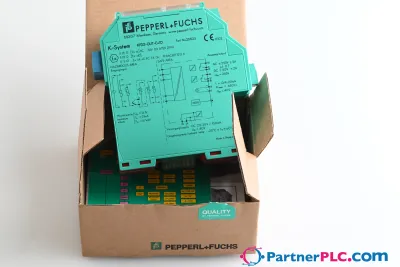 NuovoPepperl + Fuchs KFD2-GUT-EX1.D New open box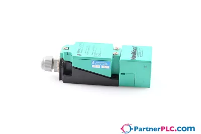
 Disponibile su richiestaPepperl Fuchs V19-W-BK15M-PUR-U-V19-G
 Disponibile su richiestaPepperl Fuchs V1SD-G-GN65M-PUR-E1S-V45-G