


Pepperl Fuchs LCL1
Richiedi un preventivo



In breve
| Disponibilità | Conferma su richiesta |
| Categoria | Capacitive Limit Switches |
| Ciclo di vita | active |
| Garanzia | 12 mesi (nuovo) · 3 mesi (usato/rigenerato) |
Spedizione e disponibilità
Quando può essere spedito LCL1?
LCL1 viene reperito su richiesta — richiedi un preventivo e ti confermeremo disponibilità e tempi di consegna esatti per questa unità specifica.
Posso ritirare LCL1 di persona?
Il ritiro presso il nostro magazzino di Groningen, Paesi Bassi, potrebbe essere possibile — contattaci prima dell'ordine per verificare disponibilità e concordare un orario di ritiro.
È disponibile la consegna espressa?
Sì — menzionalo nella richiesta di preventivo per LCL1 e includeremo le opzioni di spedizione espressa nella nostra risposta.
Il nostro impianto è fermo e ci serve con urgenza: potete aiutarci?
In caso di guasto critico, contattaci direttamente al +31 (0)50-7110348 o a sales@partnerplc.com — valuteremo un corriere in giornata o una consegna dedicata per LCL1, in base a disponibilità e destinazione.
Capacitive limit switch. Limit switch for bulk solids, Device with rod probe, Complete unit consisting of the probe and electronic insert, Integrated active build-up compensation: exact switch point, even with strong build-up, Mechanically rugged: no wearing parts, long operating life, maintenance-free. Measuring method: A metal plate at the end of the probe, within the insulation, and the surroundings (e. g. the silo walls) combine to form the two electrodes of a capacitor. If the probe is covered or free of material, then the capacitance changes and the LCL switches.. Equipment architecture: The measuring system consists of:- the device- a supply point- the connected control systems, switching units, signalling systems (e. g. lamps, horns, PCS, PLC, etc.). Construction type: device with rod probe. Operating mode: MAX = maximum safety:The device switches if the probe is covered or if the supply voltage is disconnected in a safety-oriented manner (signal on alarm).example application: overspill protectionMIN = minimum safety:The device switches if the probe is uncovered or if the supply voltage is disconnected in a safetyoriented manner (signal on alarm).example application: dry-running protection. Series: LCL1. Rated voltage: electrical connection E5: 10.8 ... 45 V DC, short-term pulse on 55 V DCelectrical connection WA: 20 ... 235 V AC, 50/60 Hz or 20 ... 55 V DC. Current consumption: electrical connection E5: max. 30 mA, reverse-polarity-proofelectrical connection WA: max. 130 mA. Surge protection: overvoltage category III. Measured variable: limit level (limit value). Measuring range: dielectric constant ≥ 1.6. Switch-on delay: correct switching after max. 1.5 s. Output signal: connection E5: switching PNP, Imax = 200 mA- overload and short circuit protection- residual voltage at transistor at Imax < 2.9 Vconnection WA: contact change-over, potential-free- Umax = 253 V- Imax = 4 A (AC)- Pmax = 1000 VA, cos φ = 1, Pmax = 500 VA, cos φ > 0.7. Signal on alarm: connection E5: < 100 µAconnection WA: relay de-energized. Electromagnetic compatibility: . Directive 2014/30/EUEN 61326-1:2006 , EN 61326-2-3:2006: . Directive 2014/30/EU: EN 61326-1:2006 , EN 61326-2-3:2006. Low voltage: . Directive 2014/35/EUEN 61010-1:2010: . Directive 2014/35/EU: EN 61010-1:2010. Electromagnetic compatibility: NE 21. Degree of protection: IEC 60529:2001. Vibration resistance: EN 60068-2-64. Climate class: EN 60068, part 2-38 (test Z/AD). Reference operating conditions: vessel type: plastic vessel, ambient temperature: 73 °F (23 °C, 296 K), medium temperature: 73 °F (23 °C, 296 K)medium pressure pe: 0 bar, medium: dielectric constant = 2.6, conductivity: < 1 µSsensitivity setting: C. Hysteresis: horizontal 4 mm (0.16 inch), vertical 7 mm (0.28 inch). Long-term drift: horizontal 3 mm (0.12 inch), vertical 6 mm (0.24 inch). Influence of medium temperature: depending on the filling material. Switching time: approx. 0.5 s when covering and uncovering the sensor. Installation conditions: . Installation positionany positionMounting locationThe capacitive limit switch can be installed in silos made of different materials (e. g. metal, plastic, concrete).: . Installation position: any position. Mounting location: The capacitive limit switch can be installed in silos made of different materials (e. g. metal, plastic, concrete).. Process conditions: . Process temperature-40 ... 130 °C (-40 ... 266 °F) -40 ... 80 °C (-40 ... 176 °F) (Dust-Ex version)Medium pressure limits-1 ... 25 bar State of aggregationsolidsSolid contents≤ ∅ 30 mmBulk density≤ 200 g/l: . Process temperature: -40 ... 130 °C (-40 ... 266 °F) -40 ... 80 °C (-40 ... 176 °F) (Dust-Ex version). Medium pressure limits: -1 ... 25 bar. State of aggregation: solids. Solid contents: ≤ ∅ 30 mm. Bulk density: ≤ 200 g/l. Ambient temperature: -40 ... 80 °C (-40 ... 176 °F) -40 ... 60 °C (-40 ... 140 °F) (Dust-Ex version). Storage temperature: -40 ... 80 °C (-40 ... 176 °F). Shock resistance: device with F34 housing: 7 J. Vibration resistance: a(RMS) = 50 m/s2, ASD = 1.25 (m/s2)2/Hz, f = 5 to 2000 Hz, t = 3 x 2 h. Degree of protection: IP66, NEMA 4. Connection: gland M20thread G1/2, NPT1/2. Material: F14 housing: polyester PBT-FRF34 housing F34: aluminumProbe: PPS GF40. Dimensions: max. ∅94 mm (3.7 inch), length 391 mm (15.4 inch). Process connection: thread R1 acc. to EN 10226, BSPT, adapter for R1-1/2 and G1-1/2 see accessoriesthread NPT1 to ANSI B 1.20.1, adapter for NPT1-1/4 see accessories. EU-type examination certificate: see instruction manuals (SI). Directive conformity: . Directive 2014/34/EUEN 60079-0:2012+A11:2013 , EN 60079-11:2012 , EN 60079-31:2009: . Directive 2014/34/EU: EN 60079-0:2012+A11:2013 , EN 60079-11:2012 , EN 60079-31:2009. Supplementary documentation: technical information (TI) manuals, brief instructions (BA, KA) instruction manuals (SI). Supplementary information: Observe the certificates, declarations of conformity, instruction manuals, and manuals where applicable. For information see www.pepperl-fuchs.com.. Designation: - LCL-Z10 cover with sight glass for F14 housing - LCL-Z11 adapter for R1-1/2, EN 10226- LCL-Z12 adapter for G1-1/2, DIN ISO 228- LCL-Z13 adapter for NPT1-1/4, steel- LCL-Z15 adapter for NPT1-1/4, 1.4571
Specifiche
General specifications
| Measuring method | A metal plate at the end of the probe, within the insulation, and the surroundings (e. g. the silo walls) combine to form the two electrodes of a capacitor. If the probe is covered or free of material, then the capacitance changes and the LCL switches. |
| Equipment architecture | The measuring system consists of:- the device- a supply point- the connected control systems, switching units, signalling systems (e. g. lamps, horns, PCS, PLC, etc.) |
| Construction type | device with rod probe |
| Operating mode | MAX = maximum safety:The device switches if the probe is covered or if the supply voltage is disconnected in a safety-oriented manner (signal on alarm).example application: overspill protectionMIN = minimum safety:The device switches if the probe is uncovered or if the supply voltage is disconnected in a safetyoriented manner (signal on alarm).example application: dry-running protection |
| Series | LCL1 |
Supply
| Rated voltage | electrical connection E5: 10.8 ... 45 V DC, short-term pulse on 55 V DCelectrical connection WA: 20 ... 235 V AC, 50/60 Hz or 20 ... 55 V DC Ur |
| Current consumption | electrical connection E5: max. 30 mA, reverse-polarity-proofelectrical connection WA: max. 130 mA |
Electrical specifications
| Surge protection | overvoltage category III |
Input
| Measured variable | limit level (limit value) |
| Measuring range | dielectric constant ≥ 1.6 |
Output
| Switch-on delay | correct switching after max. 1.5 s ton |
| Output signal | connection E5: switching PNP, Imax = 200 mA- overload and short circuit protection- residual voltage at transistor at Imax < 2.9 Vconnection WA: contact change-over, potential-free- Umax = 253 V- Imax = 4 A (AC)- Pmax = 1000 VA, cos φ = 1, Pmax = 500 VA, cos φ > 0.7 |
| Signal on alarm | connection E5: < 100 µAconnection WA: relay de-energized |
Directive conformity
| Electromagnetic compatibility | |
| Directive 2014/30/EUEN 61326-1:2006 , EN 61326-2-3:2006 | Directive 2014/30/EU |
| Directive 2014/30/EU | EN 61326-1:2006 , EN 61326-2-3:2006 |
| Low voltage | |
| Directive 2014/35/EUEN 61010-1:2010 | Directive 2014/35/EU |
| Directive 2014/35/EU | EN 61010-1:2010 |
Conformity
| Electromagnetic compatibility | NE 21 |
| Degree of protection | IEC 60529:2001 |
| Vibration resistance | EN 60068-2-64 |
| Climate class | EN 60068, part 2-38 (test Z/AD) |
Measurement accuracy
| Reference operating conditions | vessel type: plastic vessel, ambient temperature: 73 °F (23 °C, 296 K), medium temperature: 73 °F (23 °C, 296 K)medium pressure pe: 0 bar, medium: dielectric constant = 2.6, conductivity: < 1 µSsensitivity setting: C |
| Hysteresis | horizontal 4 mm (0.16 inch), vertical 7 mm (0.28 inch) |
| Long-term drift | horizontal 3 mm (0.12 inch), vertical 6 mm (0.24 inch) |
| Influence of medium temperature | depending on the filling material |
| Switching time | approx. 0.5 s when covering and uncovering the sensor |
Operating conditions
| Installation conditions | |
| Installation positionany positionMounting locationThe capacitive limit switch can be installed in silos made of different materials (e. g. metal, plastic, concrete). | Installation position |
| Installation position | any position |
| Mounting location | The capacitive limit switch can be installed in silos made of different materials (e. g. metal, plastic, concrete). |
| Process conditions | |
| Process temperature-40 ... 130 °C (-40 ... 266 °F) -40 ... 80 °C (-40 ... 176 °F) (Dust-Ex version)Medium pressure limits-1 ... 25 bar State of aggregationsolidsSolid contents≤ ∅ 30 mmBulk density≤ 200 g/l | Process temperature |
| Process temperature | -40 ... 130 °C (-40 ... 266 °F) -40 ... 80 °C (-40 ... 176 °F) (Dust-Ex version) |
| Medium pressure limits | -1 ... 25 bar |
| State of aggregation | solids |
| Solid contents | ≤ ∅ 30 mm |
| Bulk density | ≤ 200 g/l |
Ambient conditions
| Ambient temperature | -40 ... 80 °C (-40 ... 176 °F) -40 ... 60 °C (-40 ... 140 °F) (Dust-Ex version) |
| Storage temperature | -40 ... 80 °C (-40 ... 176 °F) |
| Shock resistance | device with F34 housing: 7 J |
| Vibration resistance | a(RMS) = 50 m/s2, ASD = 1.25 (m/s2)2/Hz, f = 5 to 2000 Hz, t = 3 x 2 h |
Mechanical specifications
| Degree of protection | IP66, NEMA 4 |
| Connection | gland M20thread G1/2, NPT1/2 |
| Material | F14 housing: polyester PBT-FRF34 housing F34: aluminumProbe: PPS GF40 |
| Dimensions | max. ∅94 mm (3.7 inch), length 391 mm (15.4 inch) |
| Process connection | thread R1 acc. to EN 10226, BSPT, adapter for R1-1/2 and G1-1/2 see accessoriesthread NPT1 to ANSI B 1.20.1, adapter for NPT1-1/4 see accessories |
Data for application in connection with hazardous areas
| EU-type examination certificate | see instruction manuals (SI) |
| Directive conformity | |
| Directive 2014/34/EUEN 60079-0:2012+A11:2013 , EN 60079-11:2012 , EN 60079-31:2009 | Directive 2014/34/EU |
| Directive 2014/34/EU | EN 60079-0:2012+A11:2013 , EN 60079-11:2012 , EN 60079-31:2009 |
General information
| Supplementary documentation | technical information (TI) manuals, brief instructions (BA, KA) instruction manuals (SI) |
| Supplementary information | Observe the certificates, declarations of conformity, instruction manuals, and manuals where applicable. For information see www.pepperl-fuchs.com. |
Accessories
| Designation | - LCL-Z10 cover with sight glass for F14 housing - LCL-Z11 adapter for R1-1/2, EN 10226- LCL-Z12 adapter for G1-1/2, DIN ISO 228- LCL-Z13 adapter for NPT1-1/4, steel- LCL-Z15 adapter for NPT1-1/4, 1.4571 |
Altri componenti Pepperl Fuchs
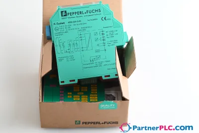 NuovoPepperl + Fuchs KFD2-GUT-EX1.D New open box
 Disponibile su richiestaPepperl Fuchs V19-W-BK15M-PUR-U-V19-G
 Disponibile su richiestaPepperl Fuchs V1SD-G-GN65M-PUR-E1S-V45-G