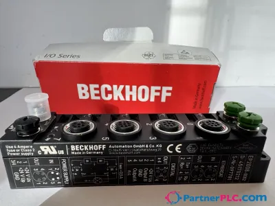
Fieldbus Box, 4-channel analog input, DeviceNet®, temperature, thermocouple, M12
Solicitar presupuesto



Datos rápidos
| Disponibilidad | Confirmación bajo consulta |
| Categoría | IP3312-Bxxx |
| Ciclo de vida | active |
| Garantía | 12 meses (nuevo) · 3 meses (usado/reacondicionado) |
Envío y disponibilidad
¿Cuándo se puede enviar IP3312-B520?
IP3312-B520 se abastece bajo pedido — solicite un presupuesto y confirmaremos la disponibilidad exacta y el plazo de entrega para esta unidad concreta.
¿Puedo recoger IP3312-B520 en persona?
Es posible recoger el pedido en nuestro almacén de Groningen, Países Bajos — contáctenos antes de realizar el pedido para confirmar disponibilidad y acordar un horario de recogida.
¿Está disponible el envío exprés?
Sí — menciónelo al solicitar un presupuesto para IP3312-B520 e incluiremos las opciones de envío exprés en nuestra respuesta.
Nuestra planta está parada y lo necesitamos urgentemente — ¿pueden ayudar?
Ante una avería crítica, contáctenos directamente al +31 (0)50-7110348 o a sales@partnerplc.com — estudiaremos un envío urgente el mismo día o un transporte dedicado para IP3312-B520, según disponibilidad y destino.
The IP3312 analog input module permits four thermocouples to be directly connected. The module’s circuit can operate thermocouple sensors using the 2-wire technique. Linearization over the full temperature range is realized with the aid of a
Especificaciones
Specifications
| Number of inputs | 4 |
| Input connections | M12, screw type |
| Connection method | M12 socket, 2-wire connection for thermocouple |
| Sensor types | types J, K, L, B, E, N, R, S, T, U (default setting type K), mV measurement |
| Measuring range | depending on sensor type; preset value is type K, -100…+1370°C |
| Resolution | 0.1°C per digit |
| Measurement error/uncertainty | ±0.5% (relative to full scale value) |
| Conversion time | approx. 250 ms, configurable up to 70 ms |
| Nominal voltage | 24 V DC (-15%/+20%) |
| Input filter | 5 variations, configurable |
| Current consumption from US (without sensor current) | see documentation |
| Power supply connection | feed: 1 x M8 male socket, 4-pin, a-coded; downstream connection: 1 x M8 female socket, 4-pin, a-coded |
| Bit width in the process image | input: 4 x 16 bit data, optional: 4 x 8 bit control/status |
| Electrical isolation | control voltage/fieldbus: 500 V, control voltage/inputs or outputs: according to I/O type |
| Extension modules | – |
| Digital peripheral signals | according to I/O type |
| Analog peripheral signals | according to I/O type |
| Configuration | via KS2000 or the controller (explicit messaging) |
| Data transfer rates | automatic detection up to 500 kbaud |
| Bus interface | 1 x M12 plug, 5-pin |
| Data transfer medium | shielded copper cable, with power supply, typ. 2 x 2 x 0.25 mm² |
| Power supply | control voltage: 24 V DC (-15%/+20%); load voltage: according to I/O type |
| Box supply current | 45 mA + current consumption of sensors, max. 0.5 A |
| Auxiliary power current | according to I/O type |
| Distance between stations | 500 m 250 m 100 m |
| Operating modes | bit strobe, polling, cyclic, change of state (COS) |
| Operating temperature | 0…55°C |
| Storage temperature | -25…+85°C |
| Vibration/shock resistance | conforms to EN 60068-2-6/EN 60068-2-27 |
| EMC immunity/emission | conforms to EN 61000-6-2/EN 61000-6-4 |
| Protect. rating/installation pos. | IP65/66/67 (conforms to EN 60529)/variable |
| Approvals/markings | CE, UL |
| Dimensions (W x H x D) | 30 mm x 175 mm x 26.5 mm |
| Material | PA6 (polyamide) |
| Installation | 2 fixing holes 3.5 mm diameter for M3 |